
Inside Rosetta: The Engine Behind Cray’s Slingshot Exascale-Era Interconnect

As the HPC community prepares for the era of exascale, over the past year, Cray scored a number of highly valuable contracts by the Department of Energy. In a clean sweep, Cray won all three of the announced United States’ next-generation exascale supercomputers – El Capitan, Frontier, and Aurora. Planned for 2021 based on Intel’s Sapphire Rapids Xeon CPUs and Xe GPUs, Aurora is planned as the US first exascale supercomputer. Shortly after Aurora, Frontier also is planned for 2021. This is an AMD-based 1.5 exaFLOPS supercomputer. Finally, the third system announced for late 2022 is the 1.5 exaFLOPS El Capitan. What’s common to all three systems is that they are all based on Cray’s latest Shasta computer system architecture.
At the heart of the new Shasta architecture is the new Slingshot interconnect. This is technically Cray’s eighth major high-performance network interconnect and has been in the works for over five years. Slingshot diverges from prior interconnects in that it embraces Ethernet as the baseline interconnect.
Slingshot actually builds on top of standard Ethernet, a first for Cray. But there is a problem. Ethernet isn’t very good for HPC workloads. Among its issues, it’s got weak synchronization mechanisms and big headers which result in inefficiency when dealing with small packets. To address these issues, Cray designed a custom interconnect called ‘HPC Ethernet’. Cray argues it brings the benefits of proprietary HPC networks to the highly interoperable Ethernet standard. But make no mistake, HPC Ethernet is still a Cray proprietary interconnect but with the added benefits that it can fall back to standard Ethernet in order to offer support for standard Ethernet-based devices (e.g., storage and network-attached accelerators). In other words, the Slingshot switch first operates using the standard Ethernet protocols but will then try to negotiate the advanced ‘HPC Ethernet’ features when a connected device supports them. The intention here is to allow the advanced HPC Ethernet features to work within the network of devices (e.g., other Slingshot switches) that supports it while being completely interoperable with Ethernet devices that do not. We will touch on some of those added features in more detail later on but the biggest addition is the introduction of better HPC-specific congestion control.
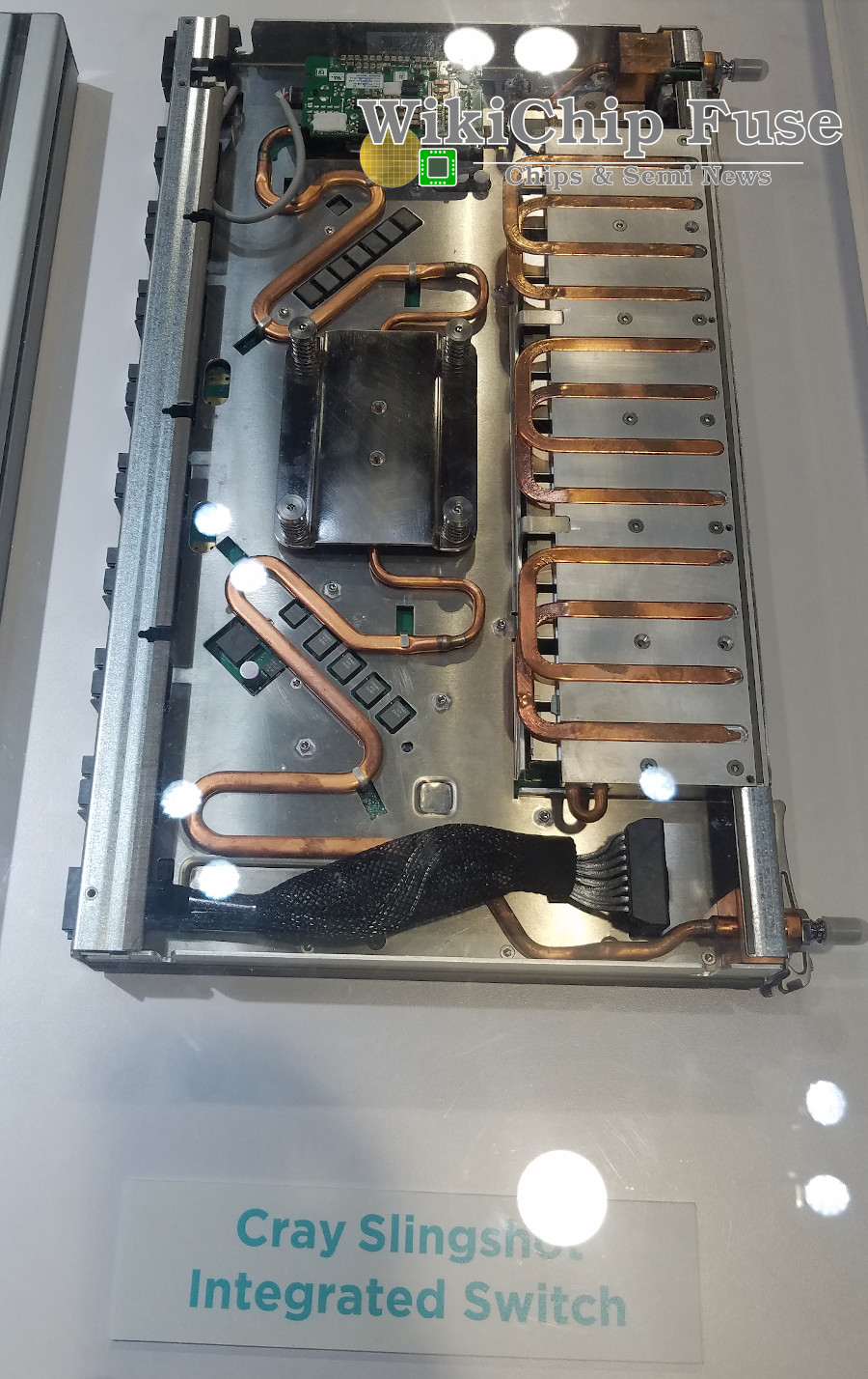
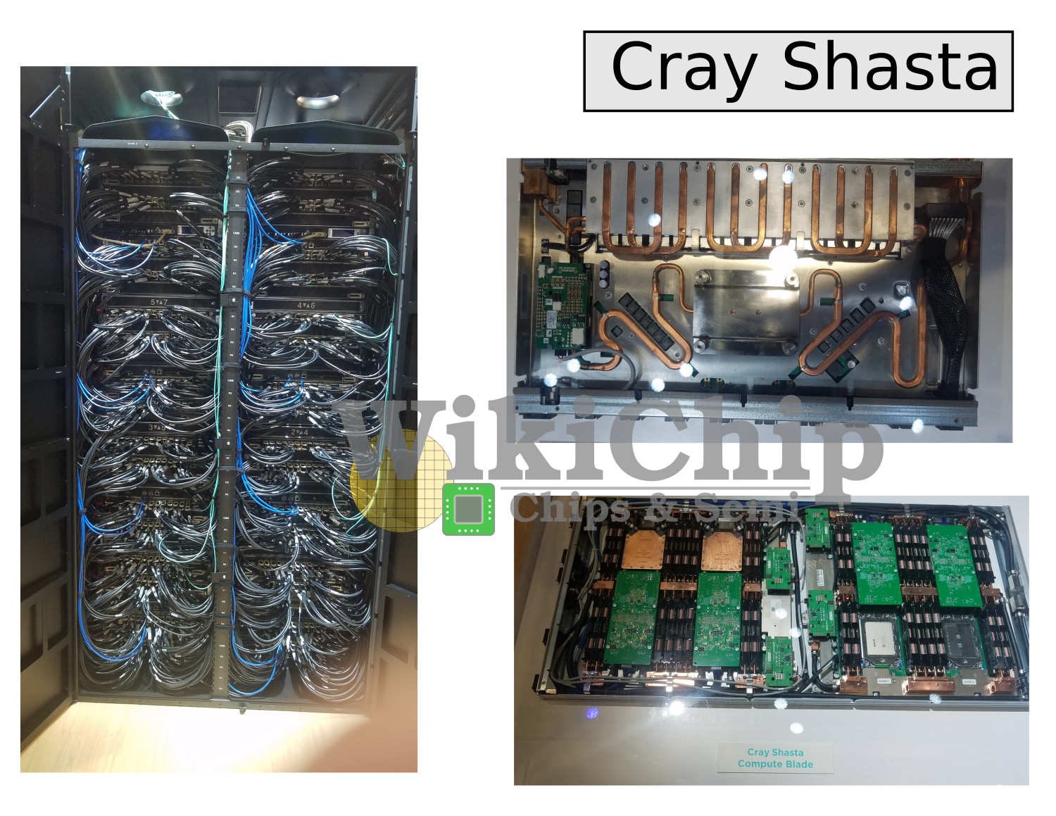
Cray builds up the Slingshot interconnects using the Slingshot switches. Those are 64-port switches. Each port is 200 Gbps using four 56G PAM4 Channels. The photo above is that of the integrated network card slingshot switch. This one is designed to go into the Shasta scale-optimized cabinets. Cray also offers the switch in a standard rackmount 1U box for Shasta systems that utilize commodity cabinets. The functionality is the same regardless. The difference is purely in the packaging.
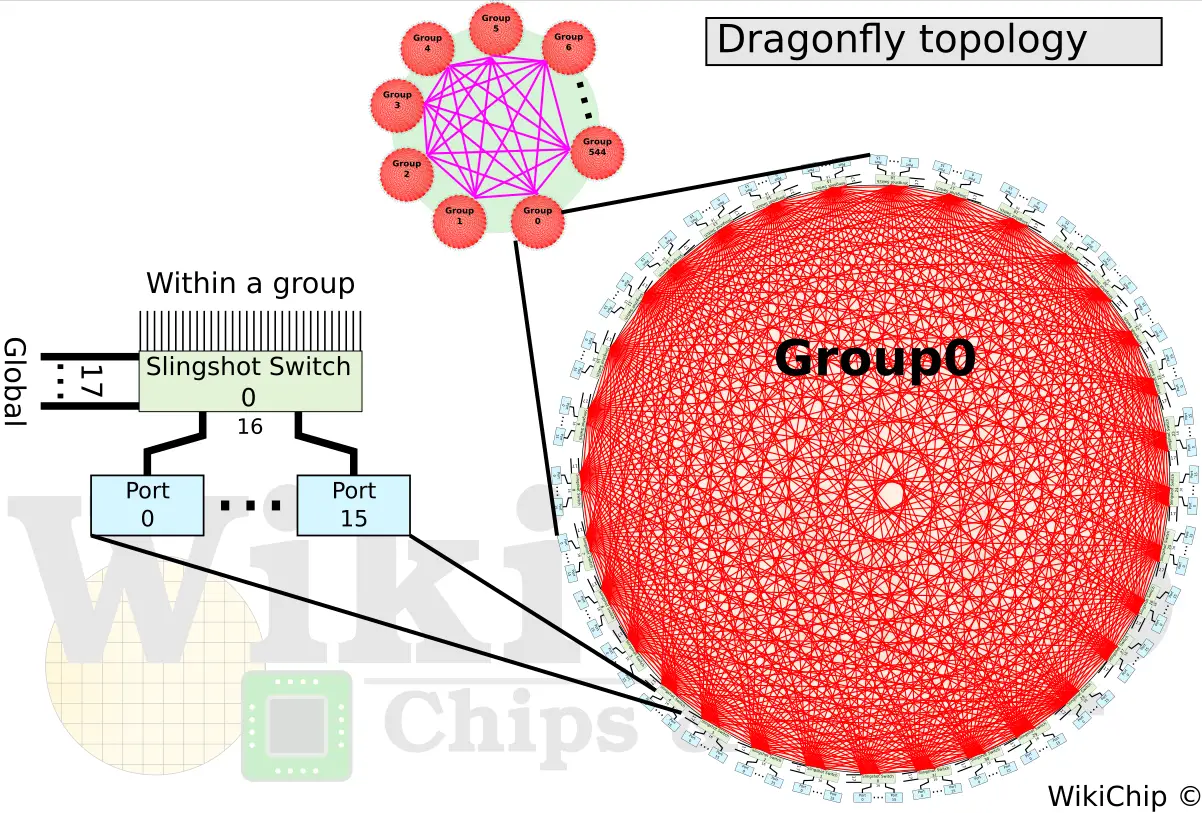
With the Slingshot switch, Cray builds up large systems using their dragonfly topology. Note that while this is the preferred topology by Cray for its systems, Slingshot supports any number of topologies such as flattened butterflies and fat trees. Slingshot will work with those topologies just fine. The use of the dragonfly topology is largely motivated by cost. It does so through the reduction of long global channels. The fewer the long optical cables, the less expensive the system is. Cray claims that up to 90% of the cables in the system are inexpensive copper cables with only 10% optical.
For those who are not familiar with the dragonfly topology, it is a hierarchical network with three levels called system, group, and router. At the lowest level is the router. For the largest-scale system, a router is connected to 16 endpoints, leaving 48 ports for inter-networking. In the middle level is the group. A group incorporates a set of routers. In the largest-scale system, a group will have 32 routers fully connected in an all-to-all using 31 of the ports from each router. This leaves 17 ports from each router (544 in total) for globally connecting all the groups at the system level in an all-to-all network. With a total of 545 groups and 32 routers per group, a Shasta system using the dragonfly topology can scale to 279,040 endpoints, all using a diameter of just 3 switch-switch hops. In other words, any hop from any switch to any other switch is a maximum of 3 hops – any switch within a group is one hop while any switch from two different groups is one short hop, one long optical hop, and again one short hop.
Rosetta
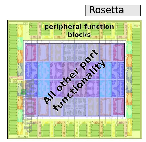
Inside the Slingshot switch is Rosetta, Cray’s custom HPC Ethernet ASIC switch. Implemented on TSMC’s 16 nm process and consuming up to 250 W, Rosetta is, as with the Switch itself, a 64 200-Gbps port switch. Rosetta utilizes a tiled architecture. In the die plot below, there are 64 tiles. 32 tiles at the perimeter of the die used for peripheral function blocks such as the SerDes, Ethernet Lookup functions, MAC/LLR/PCS. The 32 tiles within the center of the die are for all the other port functionality. Note that each tile incorporates two ports. “We got first silicon back in September 2018. We are actually going to general production with A0-silicon, which is an incredible testament to our design team,” said Steve Scott, Cray CTO.
Internally, the chip comprises 32 tiles arranged as four rows by eight columns. There are two switch ports per tile, therefore with 32 tiles, you are looking at the full 64 ports. Instead of massive crossbars, the Rosetta is implemented using a hierarchical crossbar. Every port has its own row bus which communicates across its row. There is a set of eight-column channels that are connected to the eight ports within that column. Since there are two switch ports per tile, there are two of those eight-column channel sets. Per tile, there is a 16-input 8-output crossbar which does the corner turns to the four rows (with two ports per row tile, you need eight outputs in total).
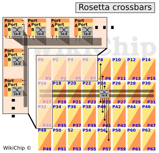
Within each tile is the 16:8 crossbar. Internally, the crossbar comprises 5 independent crossbars – requests to transmit, grants, request queue credits, data, and end-to-end acknowledgment. The chip relies on a virtual output queued architecture so data coming into the input buffers remain there until it’s ready to be sent out, overcoming the HOL blocking. Rosetta starts parsing and processing the header as soon as it arrives. This is decoupled from the data so that it can start processing while the data might still be arriving. Requests to transmit is sent out for an arbitration request. Once granted, a grant is sent back indicating the request is granted and enough space in the output buffer has been reserved. Once arrived, data is sent to the output. There is an additional queue for credits, ensuring there is always enough space for the request to arrive at the output buffer.
HPC Ethernet
We mentioned that Cray Slingshot implements this new protocol called HPC Ethernet. This protocol is a joint effort by Cray and an undisclosed company that supposedly makes DC switches. We think it’s Broadcom. HPC Ethernet is a superset of the standard Ethernet protocols specifically optimized for HPC for performance and resiliency. Within the Cray system internally and within the switches, all the packets are HPC Ethernet packets while communication with network edge devices is your standard Ethernet packets.
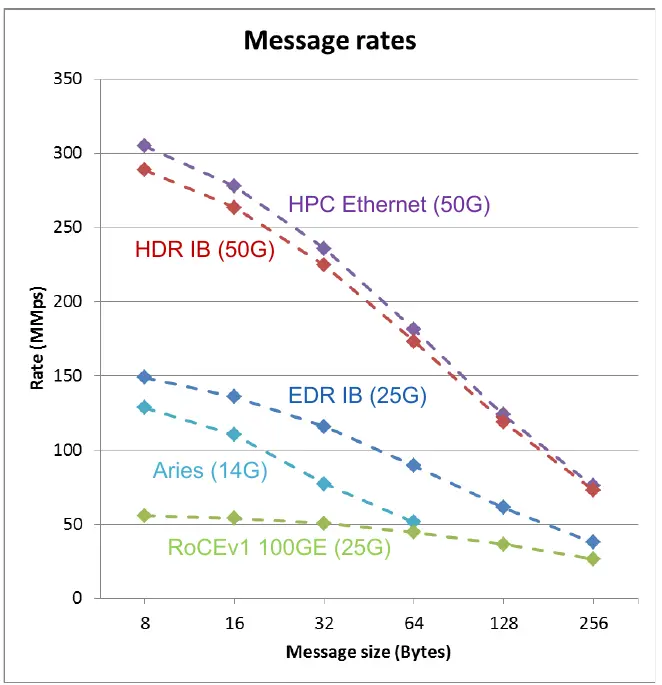
It’s ‘Ethernet-friendly’, allowing packets to easily be converted from one form to the other. Ethernet has a minimum frame size of 64 bytes (18-byte header + 46-byte payload). HPC Ethernet gets rid of that restriction, targetting 40-byte frames (or 32-byte plus sideband). It gutted the header, making it minimal in size as possible – reducing the preamble, removing the L2 header. They also introduced a credit-based flow control which is designed to be much more efficient than the existing mechanism. To help with the resiliency, there is low-latency FEC, link-level retry to tolerate transient errors (retransmit at the link level on CRC errors), and lane degrade which will drop (say form four lanes to three lanes or three lanes to two lanes) on a lane failure (e.g., laser, pin failure). Put it simply, they HPC’fied the Ethernet protocol. In the analytical graph by Cray below which plots the message size versus the million packets per second which can be sent, it’s clear that compared to standard Ethernet, HPC Ethernet is more efficient at small message sizes due to the considerably smaller header. HPC Ethernet is right up there comparable to HDR Infiniband which is another very good HPC network interconnect.
There are other features that existed in Cray’s prior interconnects that were also enhanced. For MPI and PGAS support, the adaptive routing is said to achieve high 90% utilization at scale with well-behaved traffic this gets close to 100%. There is support for fine-grain packets. This comes from the fact that less than 64B packets are supported. Typically 40B or even 32B with an 8B sideband for miscellaneous network-related data. Cray says that puts and non-fetching atomic memory operations (AMO) can support up to 500 million references per second in each direction per link while gets and fetching AMOs can do around 300 million.
The behavior and capabilities of the quality of service in Slingshot were also greatly enhanced. Slingshot introduces eight traffic classes. And those are fully configurable classes. It’s designed to allow for a number of different virtual networks with varying network characteristics. For example, each class can have a configurable priority. Its ordering may also be configured. Their minimum and maximum bandwidth constraints (e.g., guaranteeing 25% of the bandwidth minimum). The idealized demo below illustrates the behavior. In the graph on the left, both jobs are in the same traffic class. Once job 2 kicks in, each one gets half of the bandwidth until job 1 complete at which point job 2 uses up all the bandwidth just like job 1 did initially. The graph on the right has the two jobs assigned different traffic classes with job 1 having a traffic class that guarantees 80% of the traffic while job 2 is in a traffic class that guarantees 10% of the bandwidth. Here we see that job 1 gets at least 80% while job 2 gets at least 10%. The remaining bandwidth is split somewhere around the middle so you end up with job 2 getting 16% and job 1 getting 84%.

The Real Magic Is In The Congestion Control
QoS is nice but real-world workloads are much more complex, often sharing the same traffic classes, fighting over the available bandwidth. Perhaps the biggest advances in Slingshot is advanced congestion management. According to Cray, Slingshot knows what is flowing between every pair of endpoints in the system. This allows it to very quickly detect congestion, especially at the egress ports. It’s very different from existing ECN-based mechanisms which send the congestion info back to the source. It is more like having different virtual lanes for everything in the network. Once an offending traffic source is detected, Slingshot pushes back on that source of the traffic, freeing up buffer space while trying to leave affected victim traffic sources alone. Due to how Rosetta is designed, the added benefit is that it also makes the network free of any HOL blocking and by extension, keeps the latency low, especially for tail latency.
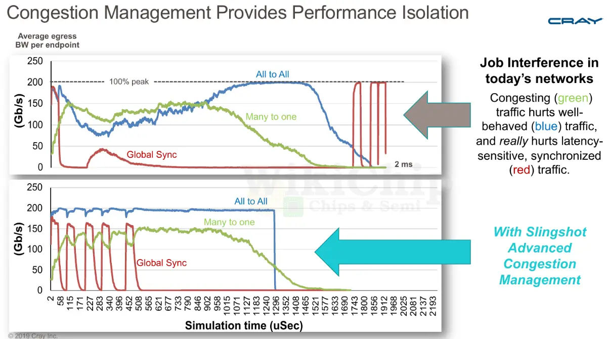
The simulation by Cray below shows the difference the congestion management in Slingshot can do. There are three sources of traffic in the graph and they are all in the same traffic class. The green traffic is causing all the congestion, the blue traffic is all-to-all well-behaved traffic, and the red traffic is latency-sensitive traffic doing things such as barrier exchanges. The graph at the top is what you will see on Cray’s prior interconnect (Aries) while the graph at the bottom is the behavior on Slingshot. Without the congestion control, once the (green) congestion traffic kicks in, the bandwidth of the well-behaving blue traffic drops by more than half. The highly latency-sensitive (red) traffic suffers the most with really high latencies. With congestion control, since the (green) congestion traffic is bandwidth bound by the egress, it actually doesn’t suffer much in performance, but now the blue and red traffic are not affected by the green traffic. It’s worth pointing out that the tail latency is also tighter.
–
Spotted an error? Help us fix it! Simply select the problematic text and press Ctrl+Enter to notify us.
–