ISSCC 2018: Intel’s Self-Powered Intelligent IoT Edge Mote
Intel Labs is perhaps the most interesting and certainly the most secretive arm of Intel. It usually gets little to no PR and not being product-driven means they can design things without being overly pragmatic. ISSCC is one of the few conferences where it is possible to catch a glimpse of some of the projects being worked on.
 At last year’s conference, they presented a low-power wireless connectivity circuit, ultra-low-power CNN face recognition processor and a CIS circuit, and later that year an ultra-low power x86 core. This year, at ISSCC 2018, Intel was back with a full-blown IoT edge mote they have designed using all the previously detailed components.
Motivation
Bringing ultra-low power AI to remote edge computing-based IoT has the promise to significantly improve many industries. Oil-well optimization, pipeline inspections, utility grids analysis, and various smart cities applications are among the common examples often cited. For their research, Intel demonstrated a use case for agricultural applications. Motes are deployed with adhesive trap papers across large agricultural fields. The motes are fully autonomous – sleeping at night and during the day periodically waking up to capture images and collect environmental sensor data. The mote then locally identifies, counts, and categorizes the data. With the help of a gateway drone, via Bluetooth Low Energy (BLE), data is securely transmitted for further cloud analytics such as generating optimal pesticide application schedules.
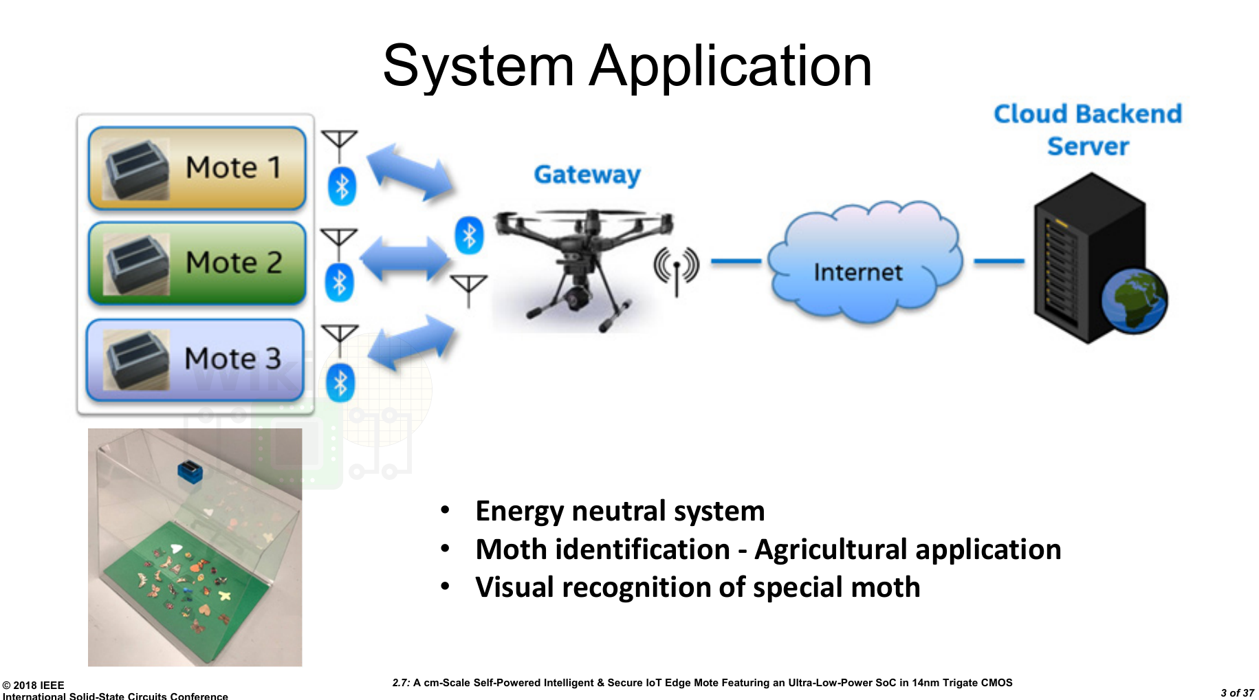
For this application, a large power source is not possible. Furthermore, local energy harvesting is usually required in order to provide sustainable energy-autonomous operation for the entire lifetime of the mote. Consequently, such platform must be extremely low-power but still powerful enough to carry the necessary edge tasks. Since wireless connectivity is required for the data collection, secure transmission is necessary.
Edge Mote Prototype
The device Intel presented is tiny – measuring just 29mm by 18mm by 18mm.
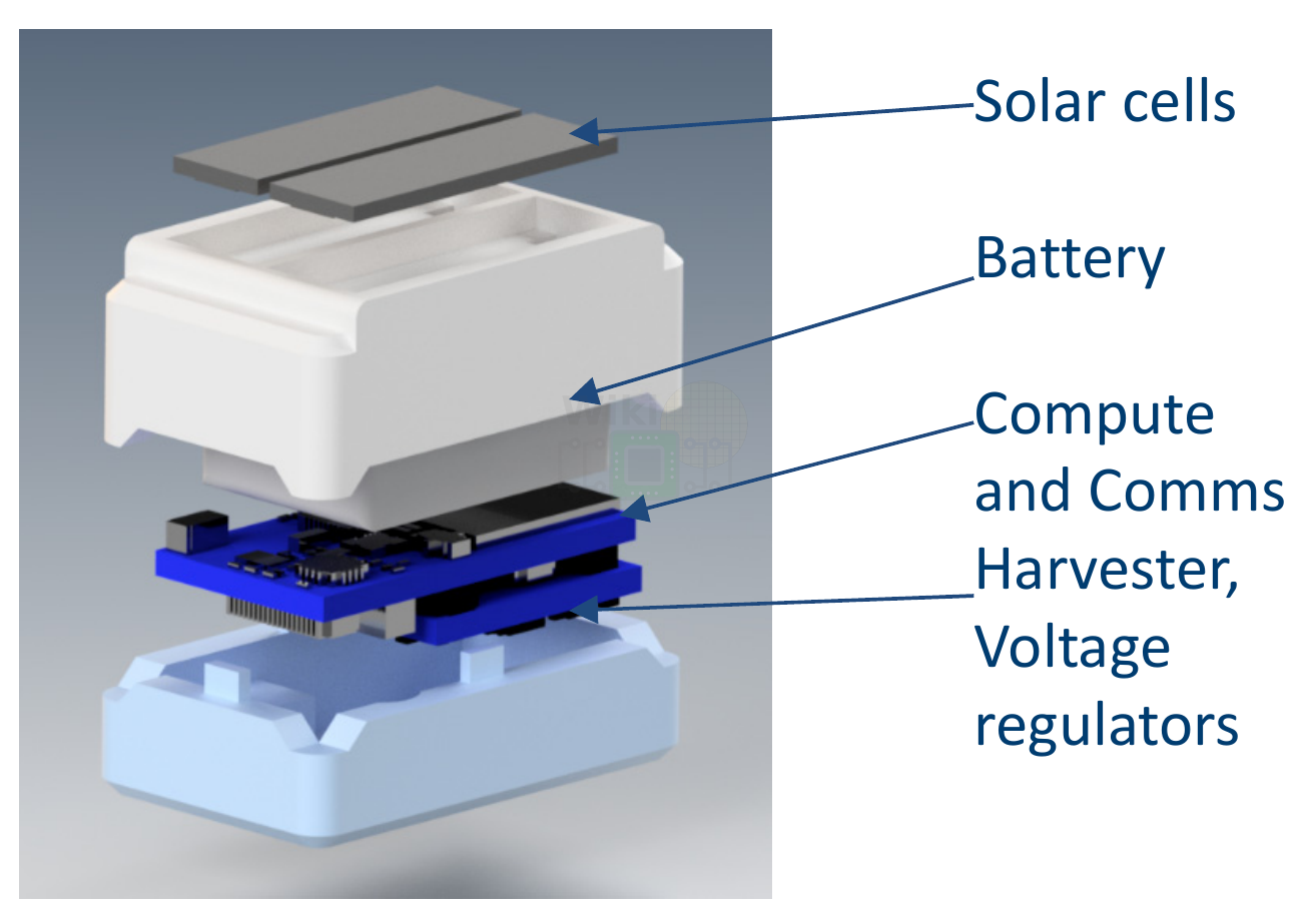
At a high level, the two major components are the compute SoC and the energy harvester. The compute SoC is connected to the Bluetooth antenna, the camera, the sensors, and other peripherals while the harvester incorporates the power delivery subsystem and the energy harvesting peripherals. Note that the diagram shows solar and wind being used, but for this device, it appears Intel only incorporated solar cells.
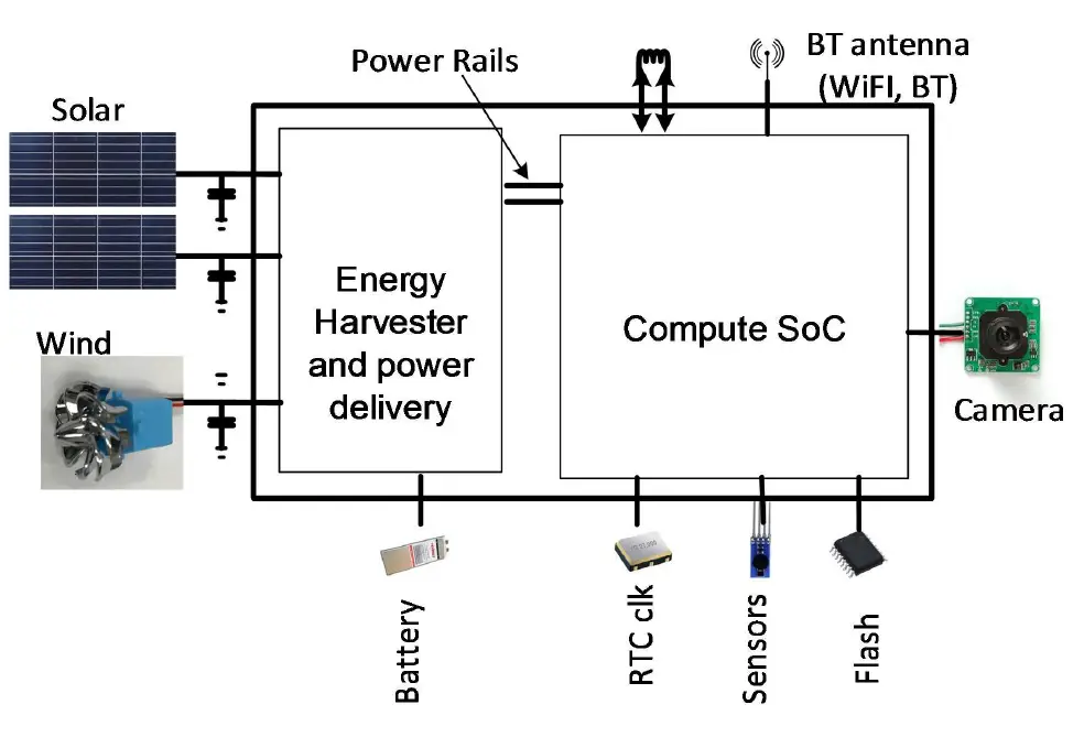
The two components are on two separate PCBs stacked on top of each other.
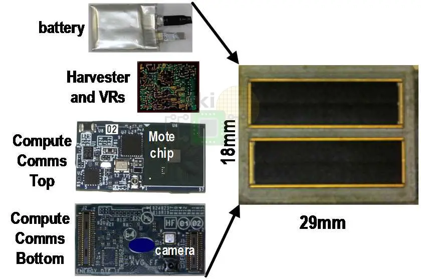
Compute SoC
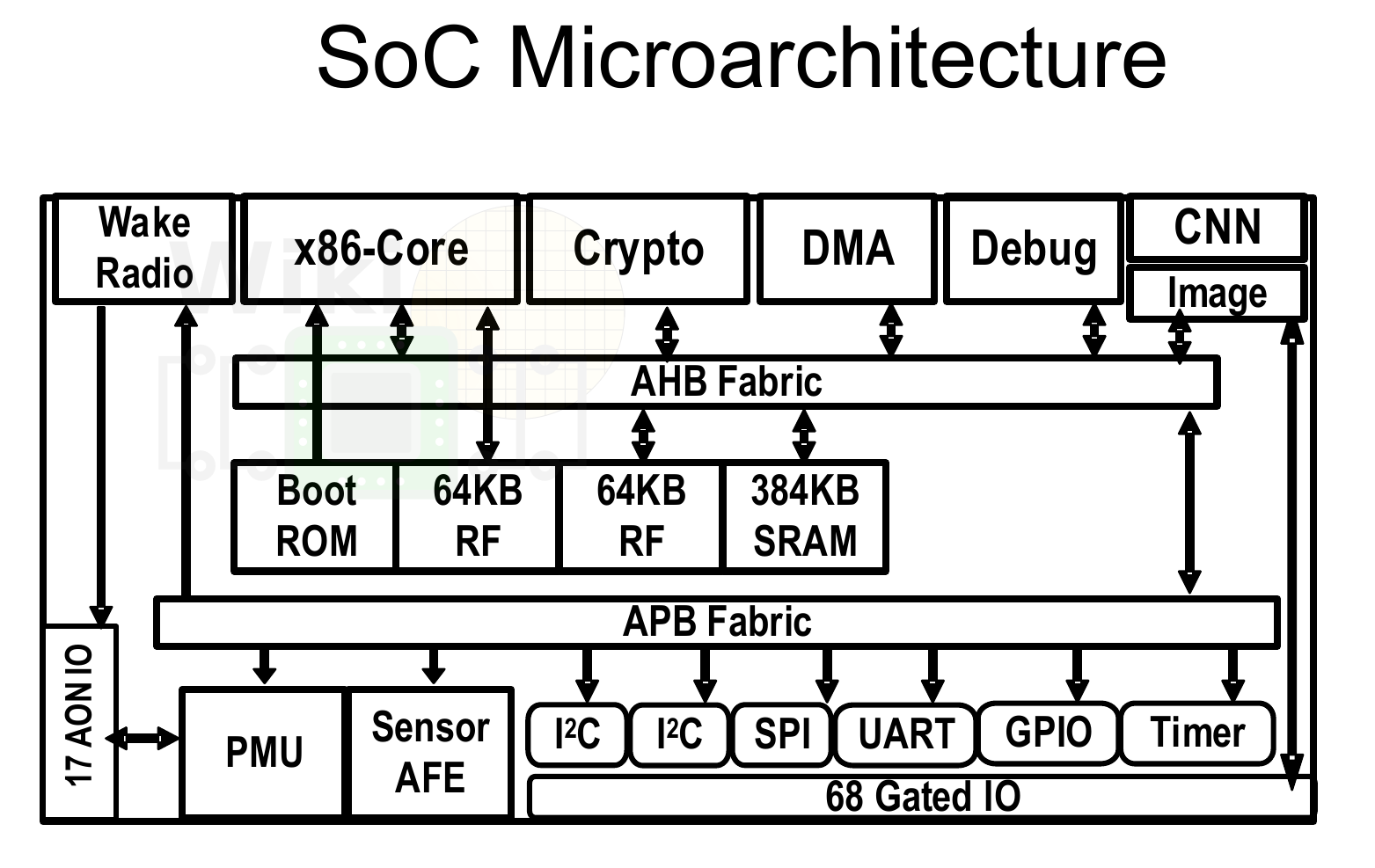
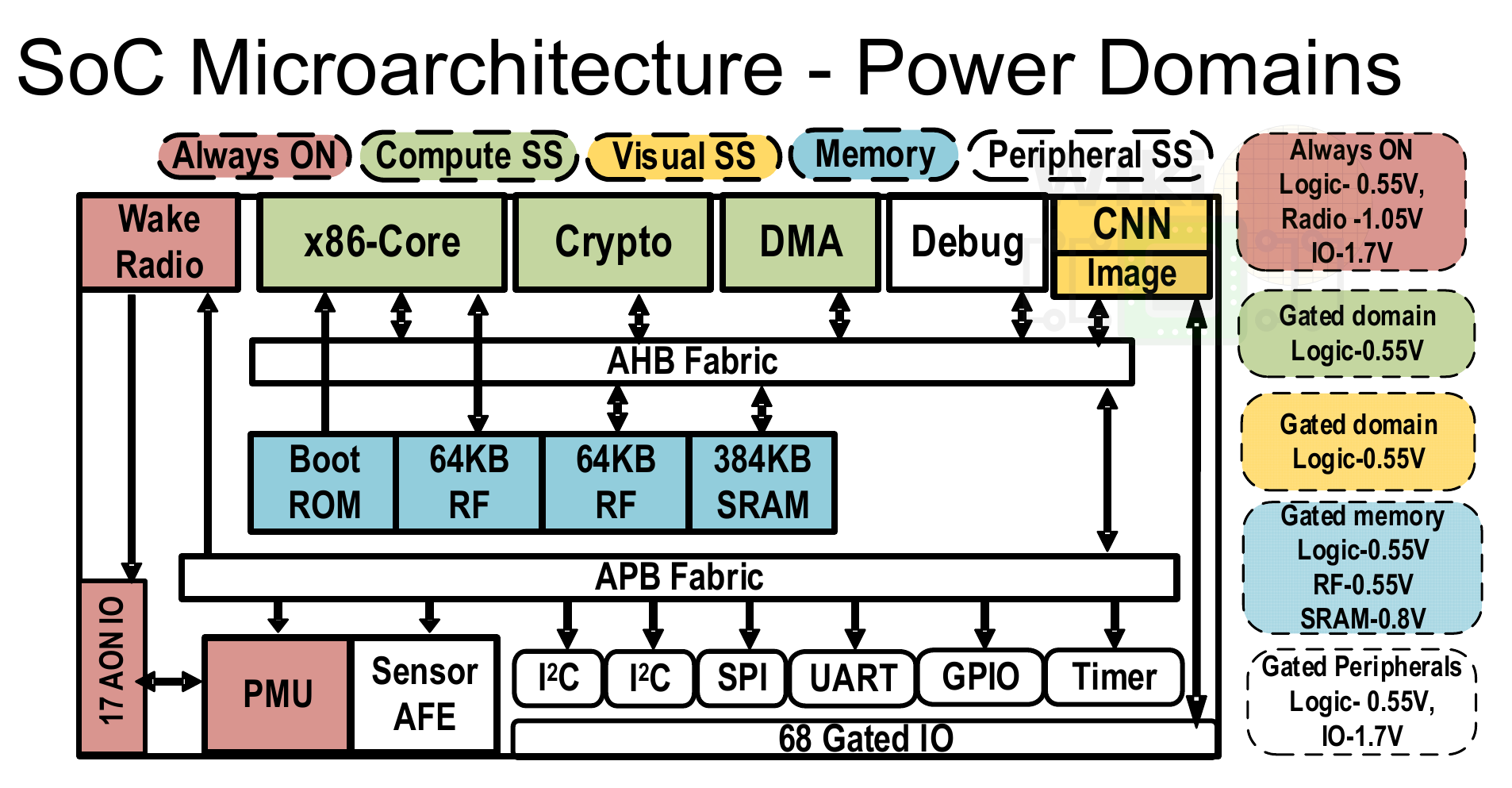
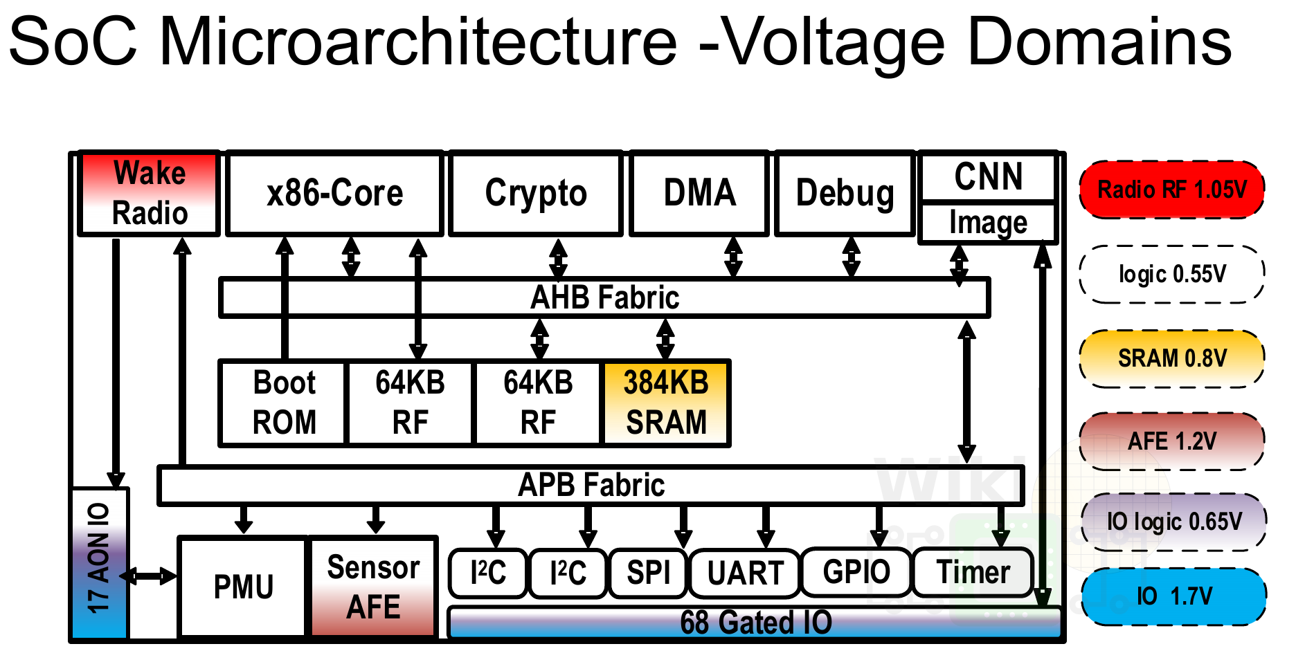
The chip consists of five subsystems grouped based on their funtionality: the always-on, compute and crypto, memory, visual, and peripheral. With the exception of the always-on subsystem, each subsystem is independently power-gated by the embedded power management unit (PMU). There are four independent voltage domains on the chip: 0.55V for logic, ROM, and register files, 0.8 V for the SRAM array, 1.05 V for radio, and 1.7 V for I/O transceivers. The always-on subsystem comprises of the wake-up radio, PMU, and AON IO. The compute subsystem consists of the x86 core, the crypto engine, and the DMA. The visiaul computing subsystem involves camera image capture and processing with processing done directly in a shared SRAM array to reduce footprint (discussed later).
| Compute SoC | ||
|---|---|---|
 |
 |
 |
| (ISSCC 2018, Intel) | ||
Power Management Unit
The design of the PMU was the most important aspect of the edge mote. For this SoC, a state machine with separate states for each of the operations was designed. Interestingly, Intel managed to achieve over 2.5x lower power than the power targets defined below.
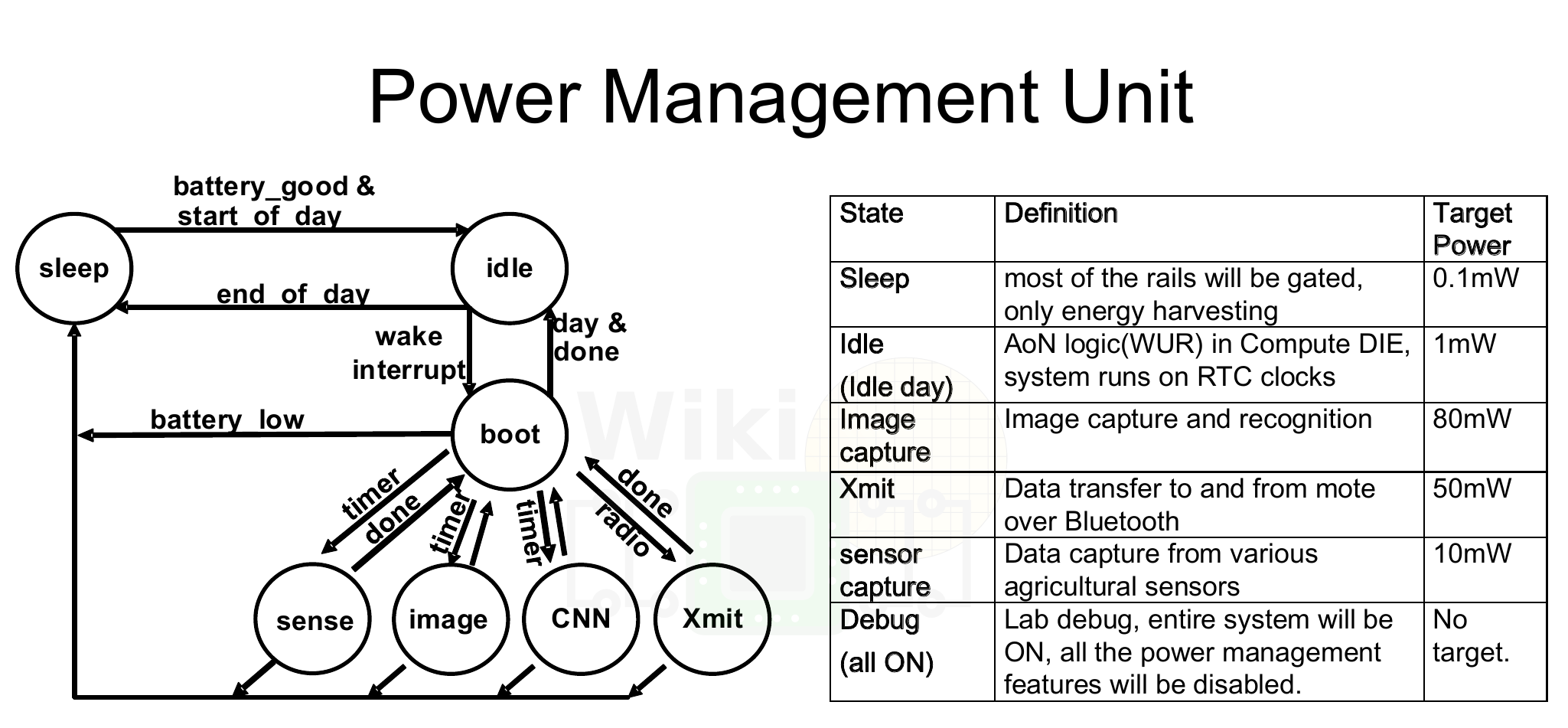
The system includes 3 always-on power rails and 14 gated rails. During sleep state, the majority of the system is turned off with only the minimum required to keep system state alive remains on. With battery_good (battery charge threshold) check and start of day, the PMU can move to an idle state where the wake radio is turned on. Upon wakeup, the system moves to the boot state. With low-power logic, the system securely boots from the boot ROM after which the core takes over the management of the system. During operation, the system will iterate over the Sense State, Image State, CNN State, and the XMIT State to capture the image and collect sensory data, to categorize the images, and to transmit the data back to the gateway.
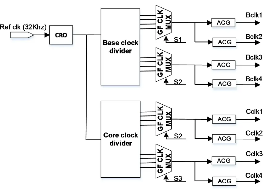
A high-frequency reference clock is generated using a low-power calibrated ring oscillator. The various functional blocks operate at the minimum required frequency to meet the necessary performance targets. Clocks are disabled for idle blocks.
–
Spotted an error? Help us fix it! Simply select the problematic text and press Ctrl+Enter to notify us.
–
