
IEDM 2018: Intel’s 10nm Standard Cell Library and Power Delivery
Mid-Height Cells
The mid-height library is a balance between area and performance. There are three P-fins per transistor and three N-fins per transistor. Like the HD library, there is an additional option for another N-fin where the logic function finds it advantageous to make use of. The mid-height cell has a height of ten diffusion lines (FP=34nm) or 340 nanometers.

Unlike the high-density cells which have the power rails at the cell border, for the mid-height cells, Intel has moved the power rails inside the cell for the Metal 0 layer, making it a dedicated power track. This allows them to optimize the cell for higher performance without compromising the efficiency of the intra-cell routing. Just like the HD library, the mid-height library features 5 signal metal tracks. In this cell, both the M0 and M1 have wider wires and vias than the HD cells for performance reasons. Compared to the HD cells, these cells have 2x higher power Metal 0 track density. Dr. Wang stated that applications for this library include high-performance graphics and data center products.

Tall Cells
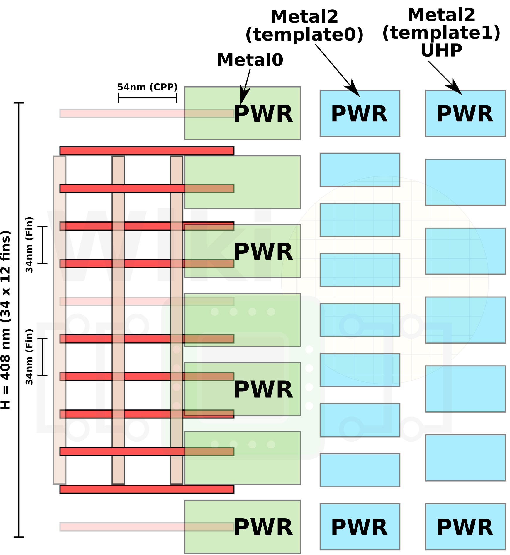
Intel’s ultra-high performance library features four P-fins per transistor and four N-fins per transistor. As with all the other cells, for cases where it’s advantageous to do so and there is a continuous poly line, there is another optional N-fin that can be used. Optimized for performance, the tall cells have the lowest interconnect resistance on power and signal wires. The UHP cell has a height of twelve diffusion lines (FP=34nm) or 408 nanometers.

These high-performance cells come with two Metal 2 templates – one optimized for the absolute best single-thread performance and the other for slightly better routability which provides better density. Additionally, for performance reasons, this cell features four power rails at the Metal 0 layers – two dedicated and two shared with adjacent cells. Compared to the HD cells, the tall cells have 3x higher power Metal 0 track density.
Dr. Wang stated that applications for this library include high-performance client processors where single-thread performance is the priority.
Std Cell Row Optimization
One of the other technologies Intel introduced with their 10-nanometer process is single diffusion break (SDB). At their 14-nanometer process, Intel defined their standard cell boundary to be at the diffusion area. This means that when adjoining two cells together, you end up with two dummy gates between the two active gates. In their 10 nm, Intel repositioned the cell boundary definition to be in the middle of the gate track. This way, when two cells abut, they form a single dummy gate isolation.
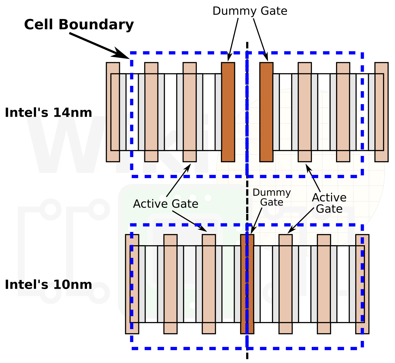
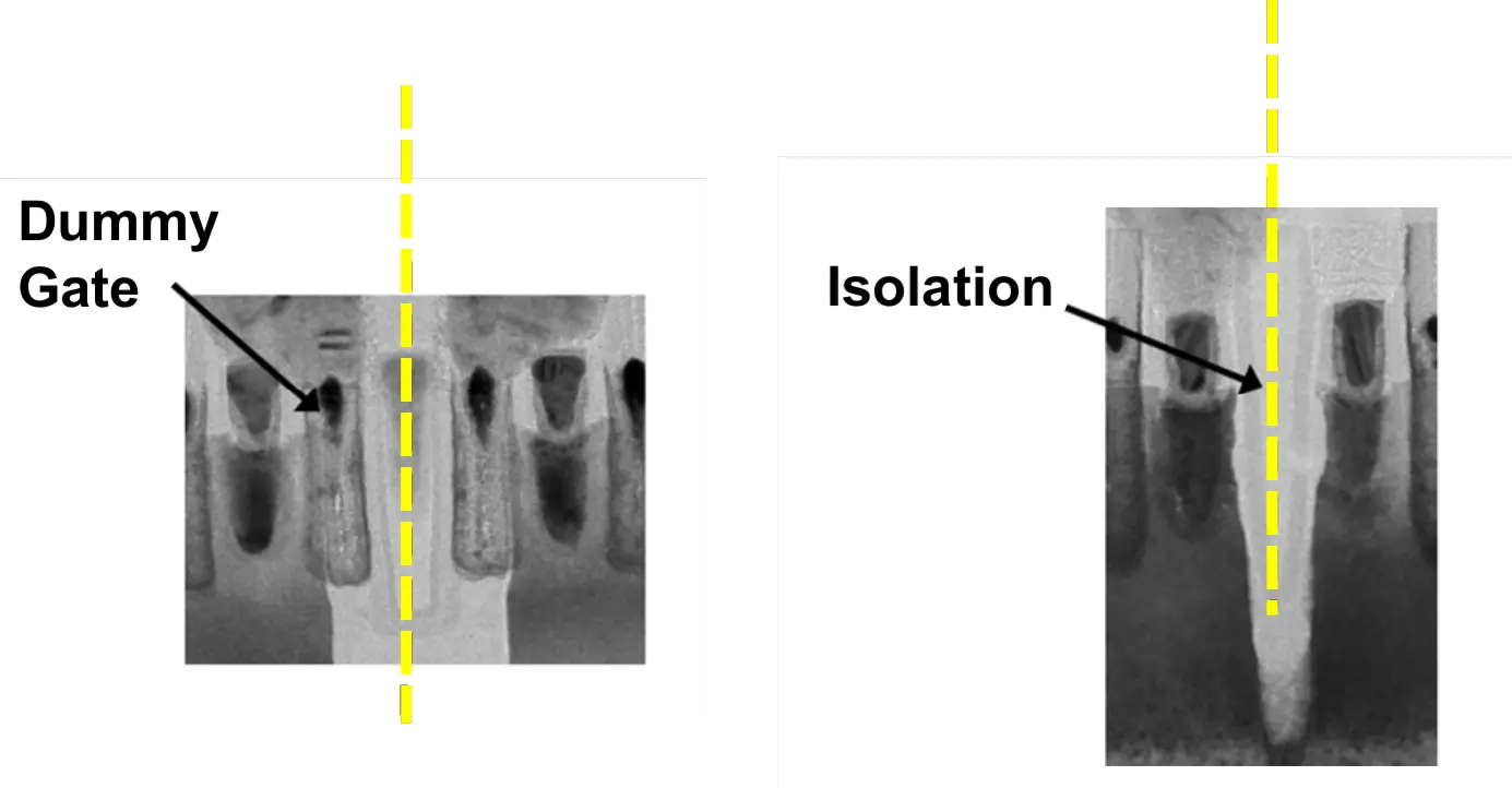
Note that the actual silicon doesn’t actually have a dummy gate but rather just an etch where the gate was positioned. This creates an isolation region to separate adjacent cells.
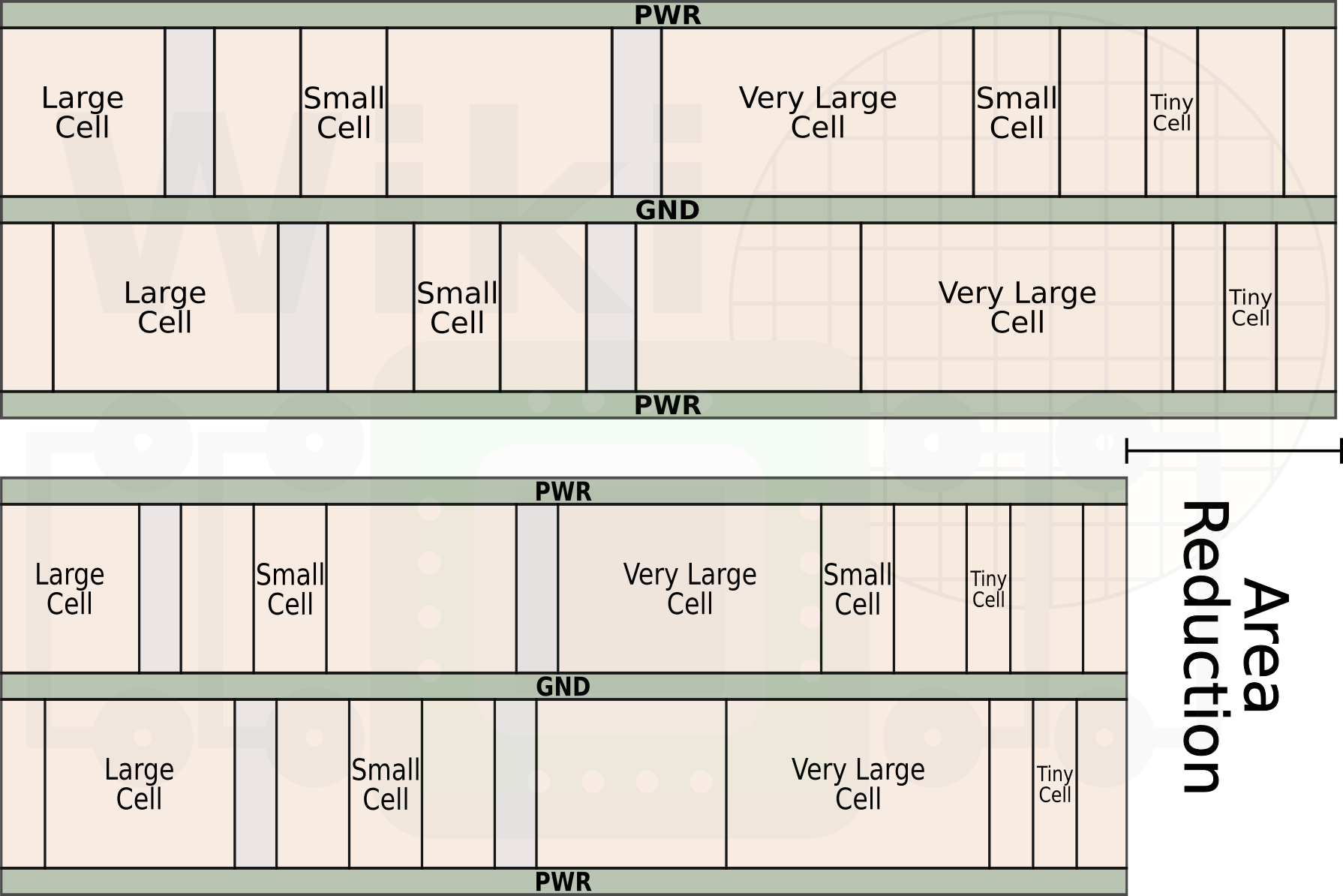
Regardless of the type of cell being used (HD, HP, UHP), based on a 40/60 simple gate to complex gate ratio, we calculate the area saving at the row level to be around 18.6%. If the row makes use of many complex (large) cell then the actual gain can be slightly higher.
Cobalt & M1 Routing
One of the major features that Intel shrunk aggressively on their 10 nm is the Metal 1 pitch – scaling from 70 nm to a whopping 36 nm (0.51x scaling). This layer is one of the two metal layers Intel is using Cobalt on. One of the major motivations for Cobalt is the significantly higher EM current density on their M1 compared to more traditional scaling (i.e., > 40nm pitch). Cobalt enables the smaller wire size while improving the electromigration reliability and interconnect capacitance. The Metal 1 track runs parallel to the poly tracks. This scaling was done in order to enable more M1 tracks per poly pitch in order to provide the cell with more pin hit locations and better inter-cell connections. Since the Metal 1 layer spans the cell and the block, this also means better block access. Due to having more M1 tracks per cell, Intel was also able to reduce the power span. Higher metal track density allows for more via placements in high drive cells which improves the wire resistance, IR-droop, and the EM driving capability.

–
Spotted an error? Help us fix it! Simply select the problematic text and press Ctrl+Enter to notify us.
–